Product Description:
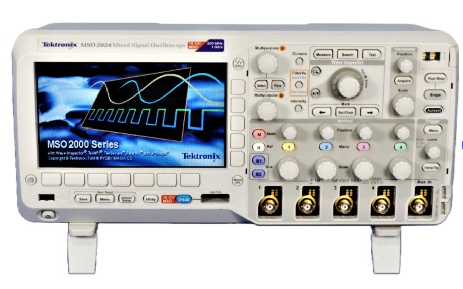
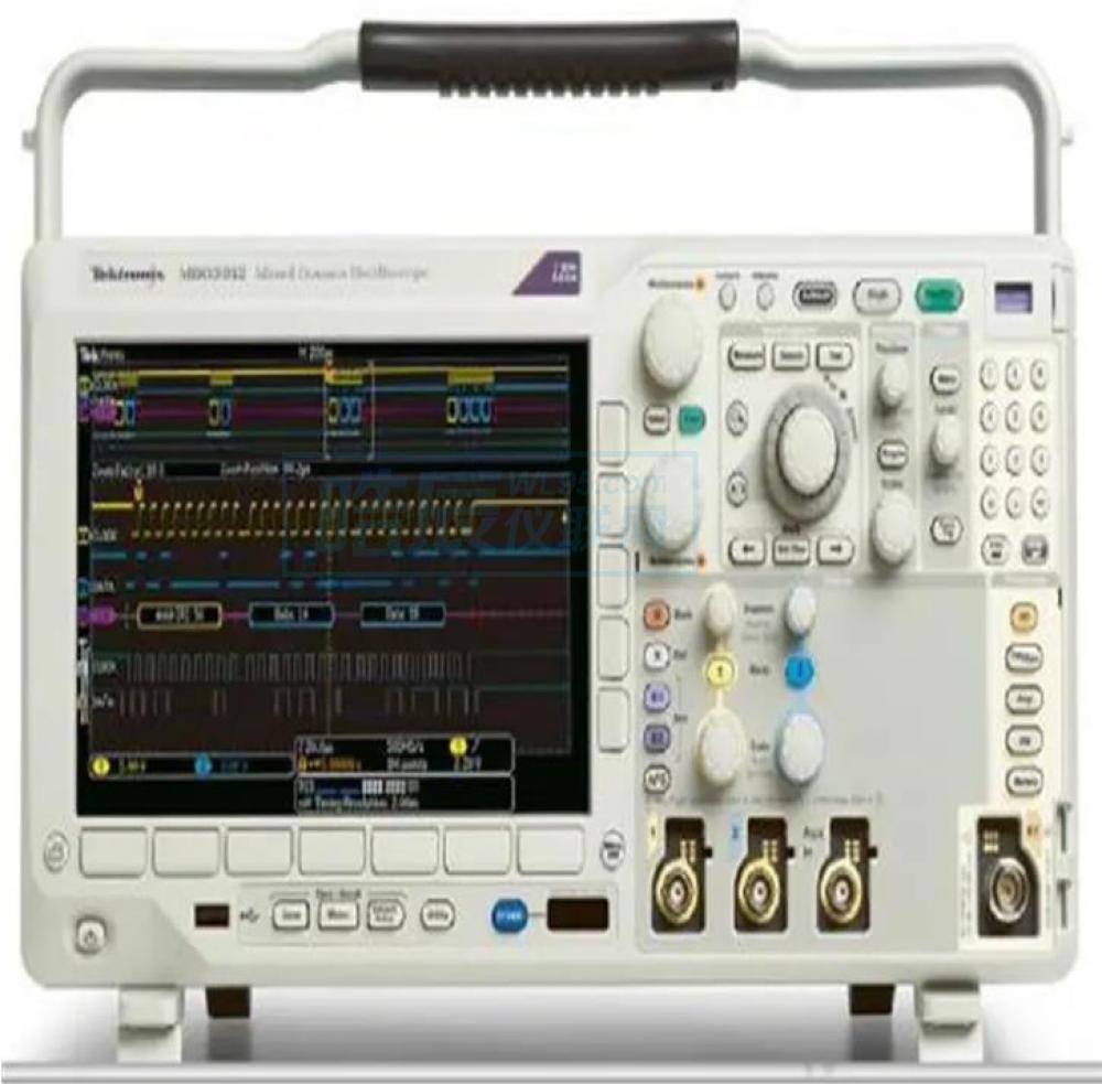
The Tektronix MSO2024 mixed signal oscilloscope offers powerful performance and a rich set of tools, including variable low-pass filters, serial trigger and decoding analysis options, for simple and fast analysis and debugging of mixed signals. The depth and available recording length on all channels allow you to capture a long window of signal activity while maintaining a fine timing resolution. The Tektronix MSO2014 mixed signal oscilloscope also adds 16 integrated digital channels to enable visualization and temporal correlation of analog and digital signals on a single instrument. This integration extends trigger functionality to all 20 channels and is ideal for debugging hybrid analog and digital designs.
Tektronix MSO2024 mixed signal oscilloscope features and specifications include:
Features:
User-friendly features and benefits:
1 megabit record length on all channels
5,000 wfm/s maximum waveform capture rate
Wave Inspector® controls for quick panning, zooming, and searching
FilterVu™ Variable Low-pass filter - removes unwanted signal noise while still capturing high-frequency events
Serial trigger and analysis - I2C, SPI, CAN, LIN, RS-232/422/485/UART
Advanced trigger kit
TekVPI® probe interface - Supports active probes, differential probes, and current probes for automatic scaling and unit
7-inch widescreen TFT-LCD color display
Small footprint and light weight - just 5.3 inches deep and weighing less than 8 pounds.
29 Automatic Measurement
FFT analysis for simplified waveform analysis
16 digital channels
Parallel bus trigger analysis
Multi-channel creation and holding triggers
Next generation digital waveform display
Connectivity:
The USB 2.0 host port on the front panel enables fast and easy data storage
USB 2.0 device ports on the rear panel:
Easy connection to PC or
Print directly to PictBridge® compatible printers
Optional 10/100 Ethernet port for network connection and video output port for exporting oscilloscope display to monitor or projector
Specifications:
Features:
Vertical system simulation channel characteristics:
Input channel: 4
Analog bandwidth (-3 dB) : 200 MHz
Calculated rise time: 2.1 ns
Hardware bandwidth limit: 20 MHz
Input coupling: AC, DC, ground
Input impedance: 1MΩ ±2%, 11.5pF ±2pF
Input sensitivity range: 2 mV/div to 5 V/div
Vertical resolution: 8 bits
Maximum input voltage, 1 MΩ : 300 V rms, peak < ±450 V
Dc gain accuracy (offset set to 0 V) :
±3% (10 mV/ cell to 5 V/ cell)
±4% (2 mV/ cell to 5 mV/ cell)
Isolation between channels (any 2 channels on the same vertical scale) : > 100:1 (< 200 MHz)
Vertical system digital channel features:
Input channels: 16 digital channels (D15 to D0)
Threshold: Indicates the threshold of eight channels in a group
Threshold: TTL, CMOS, ECL, PECL, user-defined
User-defined threshold range: ±20 V
Maximum input voltage: ±40V
Threshold accuracy: ± (100 mV + 3% of threshold setting)
Maximum input dynamic range: 80 V pk-pk (depending on threshold setting)
Minimum voltage swing: 500 mV pk-pk
Input impedance: 101kΩ
Probe load: 8 pF
Vertical resolution: 1 bit
Horizontal system simulation channel features:
Maximum sampling rate (all channels) : 1 GS/s
Maximum record length (all channels) : 1 Mpoints
Maximum duration of capture (all channels) at the highest sampling rate: 1 ms
Time base range (s/div) : 2 ns to 100 s
Time base delay time range: -10 squares to 5000 seconds
Inter-channel difference correction range: ±100 ns
Time base accuracy: ±25 ppm
Horizontal system digital channel features:
Maximum sampling rate (when using any channel D7-D0) : 1 GS/s (1 ns resolution)
Maximum sampling rate (when using any channel D15-D8) : 500 MS/s (2 ns resolution)
Maximum record length (all channels) : 1 Mpoints
Minimum detectable pulse width: 5 ns
Delay between channels: 2 ns (typical)


 服务热线:0755-86016691 电话:13715327187 传真:0755-86641139-816